News, 17 June 2026
News, 17 June 2026
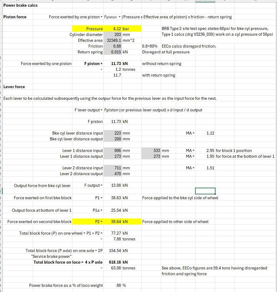
Apart from all the regular work ongoing, we've been looking further at testing the brakes - see the update a couple of weeks ago with the handbrake tests. This week we've tested the power brake, principally to confirm that the force expected at the brake blocks is correct. This comprises a series of calculations working through the system from the brake cylinder to the blocks and is nothing more than GCSE physics level calcs; air pressure acting on a piston; resultant force acting on a series of levers and finishing at the brake blocks.
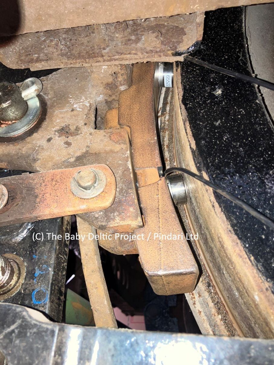
To confirm the design calcs, we used a pressure gauge on the brake cylinder to measure the force on the piston and a modified brake block to measure the resultant force.
The photo below shows the modified brake block in position, two load cells are used so that the block remains steady; the force measured at each cell is added to get the total block force.
This video shows the sequence of operations from applying air to the brake cylinder, through the full application of the brake, to releasing the air and releasing the brake. We only need to measure the force on one wheel, the bogies have been overhauled and it is reasonable to assume that the force measured at one position is also applied at all other positions. The force measured at one block is doubled to get the force on one wheel, then doubled again to get the force for the axle, then multiplied by four to get the force for the loco.
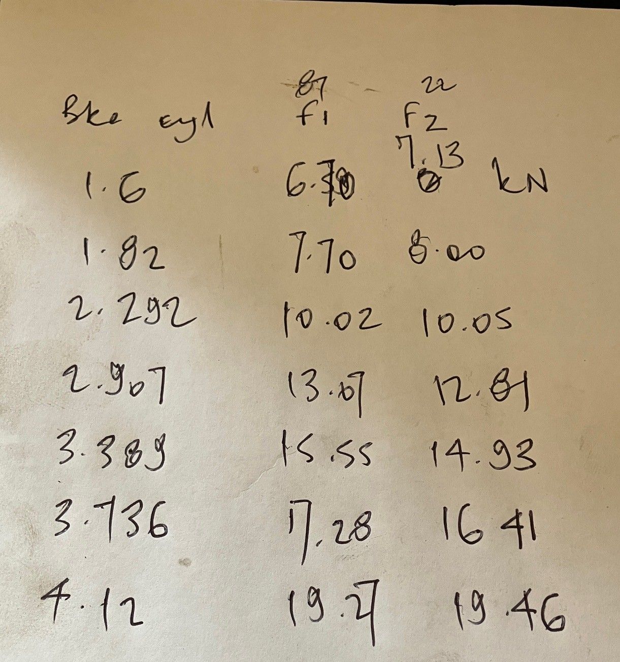
The two photos below are a badly handwritten record sheet and a screenshot of the brake calcs. Note that the sum of the load cell force (19.27 + 19.46) at 38.73kN is very close indeed to the 38.64kN predicted by the calcs.